Forces in Two Dimensions

Practice
practice problem 1
- the magnitude of the acceleration of the human cannonball inside the barrel
- the net force on the human cannonball inside the barrel
- the weight of the human cannonball
- the components of her weight that are parallel and perpendicular to the barrel of the cannon
- the force on the feet of the human cannonball while she is being launched
- the magnitude and direction of the acceleration of the human cannonball in flight
- the horizontal and vertical components of her initial velocity
- the time she spends in the air
- the distance from the mouth of the cannon to the center of a properly placed net
- her maximum height above the mouth of the cannon

solution
Use one of the equations of motion to find the acceleration of the human cannonball inside the cannon. I recommend the one traditionally known as the third.
v2 = v02 + 2a∆s
a = v2/2∆s
a = (18 m/s)2/[2(4.5 m)]
a = 36 m/s2Use Newton's second law of motion to get the net force on the human cannonball inside the cannon. Use the acceleration we just calculated.
∑F = ma
∑F = (55 kg)(36 m/s2)
∑F = 1980 NUse the appropriate equation for the weight of the human cannonball.
W = mg
W = (55 kg)(9.9 m/s2)
W = 539 NMake a drawing so you can see which trig function to use for which component of her weight.

W∥ = mg sin θ
W∥ = 539 N sin 60°
W∥ = 467 NW⟂ = mg cos θ
W⟂ = 539 N cos 60°
W⟂ = 270 NMake another drawing showing how the forces work when the human cannonball is on her way out.

The component of her weight and the normal that is perpendicular to the barrel cancel out. Nothing's happening in that direction. The component of her weight and the normal force that is parallel to the barrel must not cancel since she is accelerating in that direction. The normal force must be greater than the parallel component of her weight by an amount equal to the net force.
∑F = N∥ − W∥
N∥ = W∥ + ∑F
N∥ = 467 N + 1980 N
N∥ = 2447 NThis is roughly 4½ times her weight. Being a human cannonball requires a lot of strength.
Once she leaves the barrel of the cannon, the human cannonball is an object in free fall. Her acceleration is the acceleration due to gravity on Earth — 9.8 m/s2 down.
Make another drawing so you can see which trig function to use for which component of her velocity.

vx0 = v0 cos θ
vx0 = 18 m/s cos 60°
vx0 = 9.0 m/svy0 = v0 sin θ
vy0 = 18 m/s sin 60°
vy0 = 15.6 m/sAt the highest point in her trajectory, the human cannonball's vertical velocity is zero. Use this to find the time it takes her to get to this point. We'll call this the half time. I recommend the definition of acceleration as the equation of choice. (Negative numbers were substituted since her velocity at this time and in this direction is decreasing.)
a = ∆v/∆t
∆t½ = ∆v/a
∆t½ = (−15.6 m/s)/(−9.8 m/s2)
∆t½ = 1.59 sSave this number because we'll need it later. Double it for now to get the number this part of the question asked for.
t = 3.18 s
The distance to the net is a horizontal measurement. Use the horizontal component of her velocity with the time we just calculated and the definition of speed. There is no acceleration in this direction, so her speed is a constant value.
vx = ∆x/∆t
∆x = vx∆t
∆x = (9.0 m/s)(3.18 s)
∆x = 28.6 mMaximum height is a vertical measurement. Use the vertical component of her initial velocity with the acceleration due to gravity and the half time we calculated earlier. These numbers work with the second equation of motion. Watch the signs. Let's let up be positive.
∆y = vy0t + ½ayt2
∆y = 15.6 m/s + (−9.8 m/s2)(1.59 s)2
∆y = 12.4 mWe could also use the third equation of motion. This has the benefit of not relying on the half time we calculated earlier.
vy2 = vy02 + 2ay∆y
∆y = −vy02/2ay
∆y = −(15.6 m/s)2/[2(−9.8 m/s2)]
∆y = 12.4 m
practice problem 2
- Draw a free body diagram of the crate.
- If the angle of the ramp is set to 10°, determine…
- the component of the crate's weight that is perpendicular to the ramp
- the component of the crate's weight that is parallel to the ramp
- the normal force between the crate and the ramp
- the static friction force between the crate and the ramp
- At what angle will the crate just begin to slip?
- If the angle of the ramp is set to 30°, determine…
- the component of the crate's weight that is perpendicular to the ramp
- the component of the crate's weight that is parallel to the ramp
- the normal force between the crate and the ramp
- the kinetic friction force between the crate and the ramp
- the net force on the crate
- the acceleration of the crate
solution
Solution…
- Draw it.

-
This is an example of a classic physics problem that students have been solving since the 17th century. It starts as an equilibrium problem, since the crate isn't going anywhere.
The component of the crate's weight perpendicular to the ramp is found using the cosine function. An object's weight is entirely pushing into a surface when the surface is level (a 0° angle of inclination). None of that weight is pushing into the surface when the surface is vertical, like a wall (a 90° angle of inclination). Cosine is a maximum when the angle is zero and zero when the angle is 90°. This is how the perpendicular component works.
W⊥ = W cos θ = mg cos θ
W⊥ = (100 kg)(9.8 m/s2)(cos 10°)
W⊥ = 965 NThe component of the crate's weight parallel to the ramp is found using the sine function. An object's weight has no sideways component on a level floor (a floor with no inclination). An object's weight is entirely parallel to a wall (a floor with a 90° inclination, in a sense). Sine is zero when the angle is zero and a maximum when the angle is 90°. This is how the parallel component works.
W∥ = W sin θ = mg sin θ
W∥ = (100 kg)(9.8 m/s2)(sin 10°)
W∥ = 170 NNormal forces are normal — that is, perpendicular to a tangent drawn to a curve or surface. This crate isn't currently going anywhere, so all the forces perpendicular to the incline must cancel. For a static crate on an incline, the force normal to the incline equals the perpendicular component of its weight.
N = W⊥
N = 965 NFriction is a sideways, lateral, or tangential force — that is, parallel to a tangent drawn to a curve or surface. I'll say it again, this crate isn't going anywhere, so all the forces parallel to the incline should cancel. For a static crate on an incline, the static friction force equals the parallel component of the crate's weight.
fs = W∥
fs = 965 N
-
The component of the crate's weight parallel to the incline pulls the crate down the incline while the frictional force tries to keep it in place. Since nothing is going anywhere, these two forces must balance each other.
∑F = ma W∥ − fs = 0 fs = W∥ As the angle of inclination increases, so to does the static friction, but it can't keep doing this forever. At some angle, the parallel component of the weight will equal the maximum static friction. Friction won't be strong enough and the crate will slip.
fs max = W∥ μsmg cos θ = mg sin θ Cancel the weight.
μs cos θ = sin θ
Do some trig.
tan θ = μs
Enter numbers.
tan θ = 0.28
Compute. The angle at which the crate just begins to slip is…
θ = 16°
This number is known as the critical angle (because it marks a critical value separating two types of behavior — sticking vs. sliding), angle of friction (because you gotta call it something), angle of repose (because granular materials will settle, or repose, in conical piles with this angle), or critical angle of repose (because adding grains to a pile with this angle will make it slump).
-
The second part of this problem may or may not describe an object in equilibrium. We'll have to see.
The perpendicular component follows the sames rules it did in part a. Use cosine here.
W⊥ = W cos θ = mg cos θ
W⊥ = (100 kg)(9.8 m/s2)(cos 130°)
W⊥ = 849 NThe parallel component of the weight still uses the sine function.
W∥ = W sin θ = mg sin θ
W∥ = (100 kg)(9.8 m/s2)(sin 30°)
W∥ = 490 NThere is no way for the crate to move perpendicular to the ramp in this scenario. The normal force must therefore equal the perpendicular component of the crate's weight.
N = W⊥
N = 849 NThe angle of inclination in part d is greater than the critical angle calculated in part c. Friction is no longer strong enough to keep the crate in place. The kinetic friction in this part of the problem is now really a function of the material surfaces (the coefficient of friction) and the contact forces (the normal force).
fk = μkN
fk = (0.17)(849 N)
fk = 144 NThe forces perpendicular to the surface cancel out. The forces parallel to the surface do not. One is greater than the other. The parallel component of the weight is greater than the kinetic friction force. The difference of these two is the net force, and it drags the crate down the ramp.
∑F = W∥ − fk
∑F = 490 N − 144 N
∑F = 346 N down the rampNet force and mass determine acceleration. The three quantities are related by Newton's second law of motion.
a = ∑F m a = 346 N 100 kg a = 3.46 m/s2
practice problem 3

Draw a free body diagram for…
- the laboratory cart and
- the lead weight.
Determine…
- the weight of the lead weight;
- the weight of the laboratory cart;
- the components of the cart's weight parallel and perpendicular to the track;
- the normal force of the cart on the track;
- the net force acting on the system;
- the acceleration of the system; and
- the tension in the string.
solution
The challenge in this problem is keeping track of the different objects. Sometimes we're dealing with the lab cart (identified by a subscripted 1), sometimes we're dealing with the lead weight (identified by a subscripted 2), and sometimes we're dealing with the whole system — the cart and weight connected by a string (identified by the lack of a subscript). This level of detail is not necessary for your own personal work, but it is a good idea for me to do it so that my work is less ambiguous to you.
Why make two diagrams when you can make one?
Lab cart on the left, lead weight on the right.

Weight is mass times gravity. The SI unit of force is the newton, which is based on the kilogram and the meter per second squared. Be sure you're using the right units.
W2 = m2g
W2 = (0.100 kg)(9.8 m/s2)
W2 = 0.980 NRepeat the steps above with a different mass.
W1 = m1g
W1 = (0.500 kg)(9.8 m/s2)
W1 = 4.90 NUse sine for the component parallel to the track and cosine for the component perpendicular to the track.
W1∥ = m1g sin θ
W1∥ = 4.90 N sin 9°
W1∥ = 0.767 NW1⟂ = m1g cos θ
W1⟂ = 4.90 N cos 9°
W1⟂ = 4.84 NNormal equals the perpendicular component of the weight on an inclined surface like the one described above.
N1 = W1⟂
N1 = 4.84 NNormal and the perpendicular component of the weight cancel out on the track. Tension is an internal force for the cart-weight system. The net force is whatever's left over — the lead weight's weight minus the parallel component of the cart's weight.
∑F = W2 − W1∥
∑F = 0.980 N − 0.767 N
∑F = 0.213 NUse Newton's second law of motion to determine the acceleration of the system. The mass that's being accelerated is the mass of the cart plus the weight.
a = ∑F/m
a = (0.213 N)/(0.500 kg + 0.100 kg)
a = 0.356 m/s2Note that this is less than the acceleration due to gravity, which is as it should be. The system is not in free fall.
Tension is an internal force for the system as a whole, but tension minus the parallel component of the cart's weight is the net force acting on the cart. Apply Newton's second law to the cart by itself. (Let right be the positive direction since that's the direction the cart is accelerating.)
∑F1 = m1a T − W1∥ = m1a T − (0.767 N) = (0.500 kg)(0.356 m/s2) T = 0.944 N right Tension is also one of two forces acting on the suspended weight. The other is the weight of the weight. The difference in these two is the net force on the lead weight. Use this information and Newton's second law to find the tension. (Let down be the positive direction since that's the direction the weight is accelerating.)
∑F2 = m2a W2 − T = m2a (0.980 N) − T = (0.100 kg)(0.356 m/s2 T = 0.944 N up Two methods give the same answer, so all is well. The lab cart and the lead weight experience the same tension (same magnitude, different directions).
practice problem 4
- Draw a free body diagram for the pendulum bob.
- Derive an equation for acceleration of the vehicle in terms of the quantities given and known constants.
solution
The pendulum bob swings in the direction opposite the acceleration. In a sense, the bob is trying to catch up to the moving vehicle when it speeds up and is overrunning the vehicle when it slows down. Inertia in action.
Start with a free body diagram. We have weight down and tension at an angle. Break the tension up into components in the traditional directions of horizontal and vertical.

Apply Newton's second law of motion…
∑F = ma
but do it twice. (Let up and forward be the positive directions.)
In the horizontal direction, the horizontal component of the tension is unbalanced. It is the net force.
∑Fx = max T sin θ = ma In the vertical direction, we assume there is no acceleration. The upward component of the tension should balance the downward weight of the pendulum bob.
∑Fy = may T cos θ − mg = 0 T cos θ = mg Divide these two equations.
T sin θ = ma T cos θ mg Simplify using algebra and trig identities.
tan θ = a g a = g tan θ
Test the equation with a few representative values. A 0° angle indicates no acceleration, since tan 0° = 0; a 45° angle corresponds to a horizontal acceleration of 1 g, since tan 45° = 1; and a 90° angle is impossible, since tan 90° = ∞.
Although the idea of using a pendulum to measure horizontal accelerations is a simple one, there really was no need to make one until people regularly started to move at speeds faster than a fast horse. The first pendulum accelerometer was built in 1889 by the British mechanical engineer Frederick Lanchester (1868–1946). A pencil was attached to the pendulum bob so that it could automatically draw an acceleration-time graph on a piece of paper.
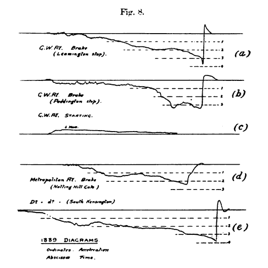
→ time →
Train 1889: (a)(b)(d)(e) braking; (c) starting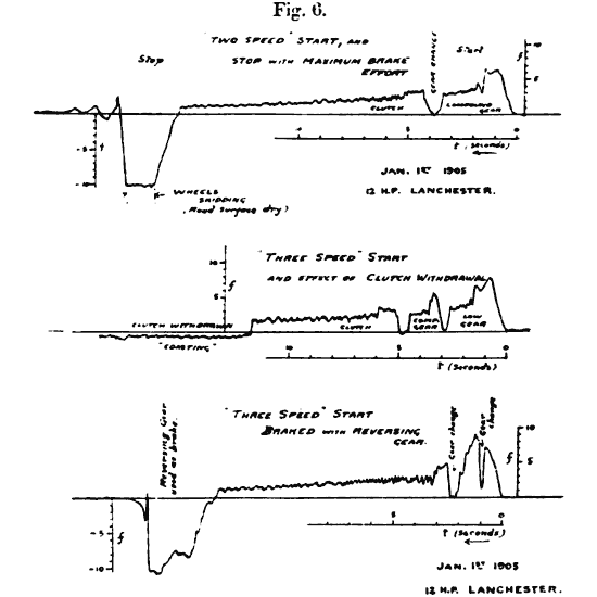
← time ←
Car 1905: top and bottom, starting and stopping; middle, starting and coastingLanchester was interested in the smoothness of braking systems on trains. In particular, he was curious about the cause of the sudden change in motion that happens right before a braking train comes to rest.
It has been remarked that a characteristic feature of brake diagrams is the suddenness of the drop at the instant of stopping. This is a very interesting and important point, inasmuch as it is the cause of the "jerk" nearly always experienced just as a train comes to rest; it was in fact in investigating this jerk in 1888 that the idea of the pendulum accelerometer occurred to the writer. At that time it was currently supposed that the jerk was the effect of the recoil of the buffer springs after stopping; whereas a very little consideration shows that it is in reality sudden change of acceleration [emphasis original] that we recognize physiologically as "jerk," that is df/dt [for some odd reason, he chose to use f for acceleration], and not change in the direction of motion. It suggests itself in fact that the term "jerk" might well be given a scientific meaning and be defined as d3s/dt3.
The suggestion stuck.