Inductance

Discussion
Introduction
Ready? Here we go.
Start with a solenoid of N turns per length ℓ. Run a current I through it and you've got yourself an electromagnet. The magnetic field B inside is given by the equation…
| B = μ0nI = μ0 | N | I |
| ℓ |
At the same time, a solenoid is also a device for capturing magnetic flux ΦB.
ΦB = NBA
The static situation is certainly interesting enough, but when it comes to flux, what we really care about is the time rate of change. This is what gives us an electromotive force ℰ through the process of electromagnetic induction. This situation is described by Faraday's law.
| ℰ = − | dΦB |
| dt |
Let's walk through these equations again, but with a time-varying twist. A solenoid with a changing current running through it will generate a changing magnetic field.
| dB | = μ0 | N | dI | |
| dt | ℓ | dt |
This changing magnetic field is then captured by the very solenoid that created it. A captured field is called flux and a changing flux generates an emf — in this case, a self-induced or back emf.
| ℰ = − | dΦB | = − N | ⎛ ⎜ ⎝ |
μ0 | N | dI | ⎞ ⎟ ⎠ |
A | |
| dt | ℓ | dt |
Rearranging things a bit gives us this equation…
| ℰ = − | μ0AN2 | dI | |
| ℓ | dt |
which may not look like much, until you realize that the terms in the first fraction are largely determined by the geometry of the solenoid. Had we chosen a different configuration of wires, the same basic thing would have happened.
| ℰ = − L | dI |
| dt |
The self-induced emf in a circuit is directly proportional to the time rate of change of the current (dI/dt) multiplied by a constant (L). This constant is called the inductance (or more precisely, the self inductance) and is determined by the geometry of a circuit (or more commonly, by the geometry of the individual circuit elements). For example, the inductance of a solenoid (as determined above) is given by the equation…
| L = | μ0AN2 |
| ℓ |
The symbol L for inductance was chosen to honor Emil Lenz (1804–1865), whose pioneering work in electromagnetic induction was instrumental in the development of the final theory. If you recall, Lenz' law states that the induced current in a circuit always acts in a manner that opposes the change that created it in the first place. This observation is why there's a minus sign in all the different versions of Faraday's law. Lenz gave us the minus sign and we honor him with the symbol L.
Inductance is best defined by its role in the equation derived from Faraday's law of induction. (This is how we will derive the inductance equations for a few easy circuit elements later in this section.) Some people don't like this and prefer definitions written in the subject-verb-object form of a simple sentence.
| L = | ℰ |
| dI/dt |
In English, we would read this as "self inductance (L) is the ratio of the back emf (ℰ) to the time rate of change of the current producing it (dI/dt)." As I already said, I don't particularly like this kind of definition, but it does help us to determine the appropriate units.
| ⎡ ⎢ ⎣ |
H = | V | = | J/C | = | (kg m2/s2)/(A s) | = | kg m 2 | ⎤ ⎥ ⎦ |
| A/s | A/s | A/s | A2 s2 |
The unit of inductance is the henry, named after Joseph Henry (1797–1878), the American scientist who discovered electromagnetic induction independently of and at about the same time as Michael Faraday (1791–1867) did in England. Faraday published his findings first and so gets most of the credit. Henry also discovered self inductance and mutual inductance (which will be described later in this section) and invented the electromechanical relay (which was the basis for the telegraph). A circuit with a self inductance of one henry will experience a back emf of one volt when the current changes at a rate of one ampère per second.
Inductance is the resistance of a circuit element to changes in current. Inductance in a circuit is the analog of mass in a mechanical system. These statements make for a good informal definition.
|
|||||
| ⇕ | |||||
|
|||||
| ⇕ | |||||
|
examples
Inductance is a function of geometry. Let's derive some inductances for a few circuit elements with simple geometries. (There aren't many.)
Since…
| ℰ = − | dΦB |
| dt |
and…
| ℰ = − L | dI |
| dt |
then anything that has this general form…
| dΦB | = L | dI |
| dt | dt |
or this form…
ΦB = L I
or this form…
| L = | ΦB |
| I |
can be used to derive an equation for L. We do this by starting with either one of two equations for magnetic flux…
| ΦB = NBA | or |
|
We then replace B with an expression appropriate to the arangement of the conductor, factor out I, and we're done.
solenoid
Determine the inductance of a solenoid where…
| A = | cross sectional area |
| N = | number of turns |
| ℓ = | length |
| n = | number of turns per length |
Start with the definition of magnetic flux for a field that is uniform in space.
ΦB = NBA
Replace B with the equation for the magnetic field inside a solenoid that was derived in a previous section, B = μ0NI/ℓ. That equation is only true for solenoids of infinite length, but assuming it applies to real world solenoids is good enough for most applications.
| ΦB = N | μ0NI | A |
| ℓ |
Rearrange it to isolate the electric current.
| ΦB = | μ0AN2 | I |
| ℓ |
The middle part is the self inductance.
| L = | μ0AN2 | = μ0Aℓn2 |
| ℓ |
toroid
Repeat for a toroid where…
| A = | cross sectional area |
| R = | radius of revolution |
| N = | number of turns |
Start with the definition of magnetic flux for a region of uniform strength.
ΦB = NBA
Replace B with the equation for the magnetic field inside a toroid derived elsewhere in this book, B = μ0NI/2πR. That equation is also only approximately true, but we're in search of utility here, not perfection.
| ΦB = N | μ0NI | A |
| 2πR |
Rearrange a bit to isolate the electric current.
| ΦB = | μ0AN2 | I |
| 2πR |
The middle part is the self inductance.
| L = | μ0AN2 |
| 2πR |
coaxial conductors
Determine the inductance of a pair of coaxial cylindrical conductors, each carrying the same current but in opposite directions, with…
| a = | inner radius |
| b = | outer radius |
| ℓ = | length |
We can't assume a uniform field strength in this case. Start with an equation for magnetic flux that can handle this. One that integrates an infinite number of infinitesimally small areas where the field is effectively constant.
| ΦB = | ⌠ ⌡ | B ⋅ dA |
Our areas to be integrated are rectangular strips of length ℓ times the infinitesimal thickness dr. Each strip captures a field of magnitude B(r) = μ0I/2πr, where the distance from the axis r ranges from the inner radius a to the outer radius b.
| b | |||
| ΦB = | ⌠ ⎮ ⌡ |
μ0I | ℓ dr |
| 2πr | |||
| a |
Factor out the terms that are constant.
| b | |||
| ΦB = | μ0Iℓ | ⌠ ⎮ ⌡ |
dr |
| 2π | r | ||
| a |
Do the definite integral.
| ΦB = | μ0Iℓ | ⎛ ⎝ |
ln b − ln a | ⎞ ⎠ |
| 2π |
The difference in two logs is the log of their ratios. (That's not quite the right way to say it.)
| ΦB = | μ0Iℓ | ln | ⎛ ⎜ ⎝ |
b | ⎞ ⎟ ⎠ |
| 2π | a |
Factor out I.
| ΦB = | μ0ℓ | ln | ⎛ ⎜ ⎝ |
b | ⎞ ⎟ ⎠ |
I |
| 2π | a |
The middle part is the self inductance.
| L = | μ0ℓ | ln | ⎛ ⎜ ⎝ |
b | ⎞ ⎟ ⎠ |
| 2π | a |
For some applications, it may be more useful to know the inductance per length of a coaxial conductor.
| L | = | μ0 | ln | ⎛ ⎜ ⎝ |
b | ⎞ ⎟ ⎠ |
| ℓ | 2π | a |
parallel conductors
Determine the inductance of two parallel conductors where…
| d = | separation between conductors |
| a = | radius of either conductor |
| ℓ = | length of either conductor |
I haven't figured out how to explain this one yet. Here's the answer.
| L = | μ0ℓ | cosh−1 | ⎛ ⎜ ⎝ |
d | ⎞ ⎟ ⎠ |
| π | 2a |
The function cosh−1 is the inverse hyperbolic cosine, by the way. Fun stuff.
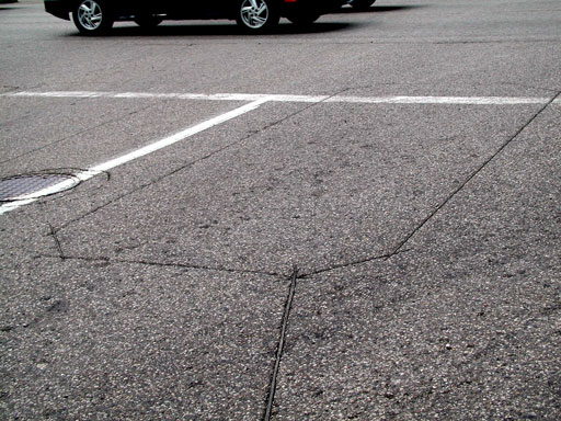
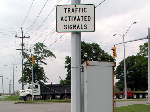
inductive loop detector
Traffic at some intersections is controlled with the aid of inductive loop detectors (ILD). An ILD is a loop of conducting wire embedded just a few centimeters below the pavement. When a vehicle passes through the field, it acts as a conductor, changing the inductance of the loop. A change in the loop's inductance indicates the presence of a car above. This information can then be used to activate traffic signals, monitor traffic flow, or issue automated citations.
 |
 |
 |
 |